When Koenigsegg announced the Jesko at the Geneva auto show, a number of us at BMWBLOG zeroed in on the Light Speed Transmission. The idea of an automated nine-speed, multi-clutch gearbox that can shift from any gear to any other gear with a prolonged tug of the shift paddle piqued our interest. How does Koenigsegg pull off its super fast, compact, and light gearbox? We had to find out.
Editor’s Note: Even though this doesn’t really have to do with BMW specifically, we were so fascinated by the tech we had to dig deeper into it by getting our very own gear-head — Hugo Becker — on the case. This is about to get techy, so buckle up.
Before we try to explain how we believe the Koenigsegg Light Speed Transmission works, it may be helpful to review how a regular manual transmission works. Usually there is a flywheel and a clutch, contained inside a bell housing and that is either part of or attached to the transmission case which contains gear sets that transfer power at various speeds to the differential.
In the attached illustration found on the web, the transmission contains an output shaft and a layshaft, The gears on the output shaft freewheel on that shaft (they are not fixed to the shaft but spin freely on it). In a constant mesh gearbox (the type we are interested in), there is a corresponding fixed gear on the layshaft for each gear on the output shaft.
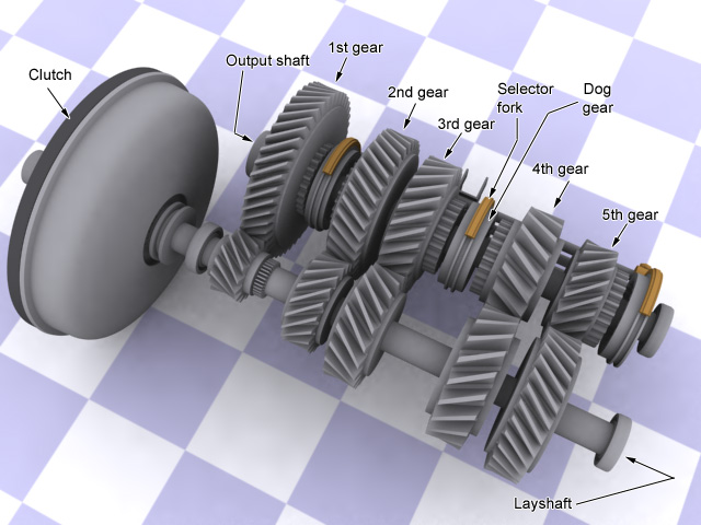
When you depress the clutch pedal, the output shaft is decoupled from the engine. When you move the gear shift lever a fork will move a lock ring – which is locked to the output shaft (but is free to move fore and aft, within a narrow range, on the shaft) – from one gear to the other which then locks the selected gear onto the output shaft. You release the clutch pedal which re-engages the engine output to the output shaft. With the gear you selected locked to the output shaft, the layshaft will now spin at the same speed as the output shaft.
The locked gear on the output shaft transfers power from the engine to the layshaft, on to the differential, and then the wheels & tires. When no gear is locked on the output shaft you are in neutral. And, fortunately, the gear selector only allows one gear at a time to be locked onto the output shaft.
The single clutch and gear selector could be implemented differently. Let’s say that each gear has a clutch associated with it. You could then do away with the single clutch between engine and transmission as well as the gear selector. The default state is for the gear to be selected only when the clutch pedal is depressed (meaning you’d have to leave your foot on it). You would also need as many pedals as you have gears; definitely not practical.
Now onto the Light Speed Transmission; it has nine forward speeds, reverse, no flywheel and eight clutches. So how do we think it works? In the place of the flywheel the crankshaft would have a small gear protruding from the end of it. In mesh with that gear on the crankshaft are two other gears, one that is connected to the shaft that houses the first three gears (1, 2, and 3) and one that house the next three gears (4, 5, and 6). The gear that drives the shaft with the first three gears ratios is 2.0978 times as large as the gear that drives the shaft with the next three gear ratios (more on this later).
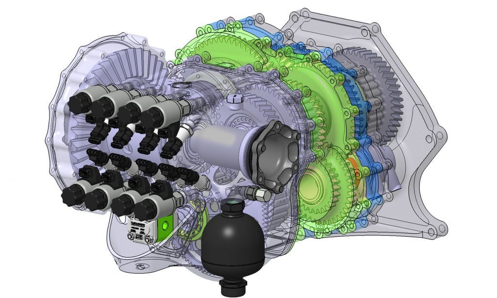
The gears on the two shafts, spun by the engine, freewheel until they are engaged by a clutch. Reverse is a separate gear with it’s own clutch. We have now accounted for the first six forward gears and the six clutches associated with them and reverse gear and its clutch. That leaves one clutch in the Light Speed Transmission that has not been accounted for.
The last clutch, clutch eight, is used by the Light Speed Transmission to select one of two output ranges, low or high. (Not unlike a transmission found on a tractor-trailer truck.) By engaging the ‘low’ output, the Light Speed Transmission serves up its first six forward gears. When the ‘high’ output is engaged the Light Speed Transmission reuses, we believe, the 4th, 5th, and 6th gears as 7th, 8th, and 9th.
That’s all well and good but why do we think this is how Koenigsegg implemented this? Looking at a couple of pictures helps explain that. Road & Track published a picture of the gear ratios (https://www.roadandtrack.com/
The gear ratios are:
1: 4.7200
2: 3.6441
3: 2.8744
4: 2.2500
5: 1.7371
6: 1.3702
7: 1.0783
8: 0.8325
9: 0.6566
Start with the difference between the first three gear ratios (1, 2, and 3) and the next three ratios (4, 5, and 6). That difference for each gear 1 and 4, 2 and 5, 3 and 6 is 2.0978. That is what leads us to believe that there are only two shafts connected to the crankshaft. Each of these gears has it’s own clutch.
Those six gears are in constant mesh on gears located on what we’ll call the output shaft. In a normal constant mesh gearbox each drive gear would have a corresponding gear in mesh on the shaft directing power to the differential. But looking at the difference between the individual gears leads to something interesting. The ratio between gears 1 to 2 is 1.295, which is the same for the difference between gears 4 and 5. The difference between gears 2 and 3 is 1.267, again the difference between gears 5 and 6 is the same. That leads us to believe that the output has only three gears fixed on it.
Then we looked at the relationship between the first three and the last three gears and every set (1 and 7, 2 and 8, 3 and 9) return the same result 4.3773. And since we know there is a fixed ratio between 1 and 4, 2 and 5, and 3 and 6 we should expect that comparing 4 and 7, 5 and 8, and 6 and 9 would return the same result. And it does, 2.0866. Therefore it is logical to assume that the lower of those two differences would comprise the ‘taller’, ‘low’ range gears for the two range output if you want to ensure a compact gear case.
To get an idea of how it might work in practice lets label the shafts with the six forward gears as A and B, the gears/clutches are 1 through 6 (gears 7, 8, and 9 are a reuse of 4, 5, and 6). The clutch that connects to the differential is either in low, L, high, H, or neutral N.
To define shift sequences the gear to be disengaged is in italics, the gear to be engaged is in bold, and the state of low, high or neutral is given in italics when it changes state then bold (in it’s changed or default state) for the output clutch.
To start the car:
A1 – N (and shaft A is spun hydraulically or electrically to turn over the engine)
Going from first to second:
A1 – A2 – L
Going from seventh to fourth:
B4 – H – L
Going from third to fifth:
A3 – B5 – L
Going from fifth to eighth:
B5 – L – H
Now here’s the hard part. This motor makes a ton of torque so straight cut gears won’t do (not enough surface area on the teeth). The gear teeth will have to be cut at a slight diagonal (but less than most manual tranny gears so it will sound like a Muncie rock crusher!). But helical cut gears introduce slide loads that have to be absorbed by the tranny case. That takes some high dollar ciphering to get right. Then of course is all the software required to make the thing dance.
Is this a revolutionary gearbox? No, but better, it is extremely clever! So when do we find one of these in an M5? Well one suspects since the cost of the Koenigsegg Light Speed Transmission represents the purchase price of an M5 or two we shouldn’t get out hopes up. But what a neat piece of technology.